May 14, 18, and 25,
2002 Meeting Notes
(Combined, late update due to crunch mode before E3 at Id
Software…)
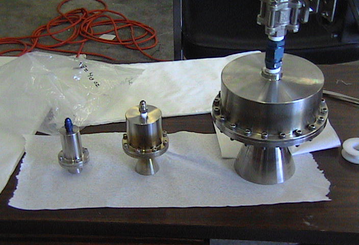
Two Inch Engines
We got a dozen 2” ID cat pack engines in from DynaTurn. We assembled a cat pack for it with 64
silver screens (exactly what we could cut from two 12” square sheets of screen)
and 52 stainless screens, and we got smooth running and clear
catalyzation. We will be using these as
attitude engines on larger vehicles, or if we need the control authority to fly
a smaller, unstable vehicle under heavy aero loads. Our solenoids don’t really flow enough for these 0.66” throats,
so they wind up with relatively low chamber pressures.
Rotor Testing
Neil re-plumbed the rotors with 0.035” wall stainless tubing
to get higher flow rate. The thinner
wall allows us to use an AN flare fitting at the engines, which we can add a
jet to. The 0.065” wall couldn’t be
flared, and required using swage-lok fittings.
Russ reworked the tach sensor board, and it seems to be
stable now, although it requires a higher rpm to start getting a signal. There may be an issue with possibly getting
a double pole signal from the magnets we are using, so we will be changing to
different magnets in the future.
I made some changes to the logging program, and we tested
everything at the shop on the vehicle mount at low rpm. (graph 1, no load cell
data)
We went out to our test range and set the rotor up on the
vertical test stand for higher rpm testing.
One process improvement we have made is to leave our test stand propellant
tank permanently mounted on the trailer, so we can just swap the short hose to
horizontal test stand for a long hose to the external vertical test stand.
media.armadilloaerospace.com/2002_05_25//OnVehicle.xls
We are still using the smaller Pro-Race solenoid, so we
expected it to be flow limited well below its structural rpm limit.
The first run had a 300 rpm limit set, and began with 178 psi
in the tank on one liter of peroxide.
It took 8 seconds for it to climb to 300 rpm, at which point it made a
couple control clicks before propellant depletion. It made 175 pounds of lift.
media.armadilloaerospace.com/2002_05_25/rpm.xls
The next run had the rpm limit raised to 500 rpm, and began
at 195 psi with two liters of peroxide.
The rpm climb was clearly tailing off, and it only reached 422 rpm and
280 pounds of lift after 16 seconds of accelerating.
media.armadilloaerospace.com/2002_05_25/miss500.xls
We raised the tank pressure on the next run to 400 psi on
two liters of peroxide. It took 4
seconds to accelerate to 300 rpm, and continued for 4 seconds more, then threw
the blades off right around 500 rpm.
Thrust was rough, peaking at 317 pounds just before falling apart.
media.armadilloaerospace.com/2002_05_25/explode.xls
The data is not entirely clear about the exact sequence of
events. It shows it between 476 and 468
rpm for a couple triggers, then a jump to 714 rpm and a solenoid inhibit, then
a jump to 1304 rpm, which was the last signal that the tach sensor got. The tach sensor could give a bad reading if
things were shaking badly enough to get a double pulse off of a single
magnet. The question is: did the rotor
just make it to 500 rpm between samples, cause a solenoid inhibit, which caused
the structural failure somehow, or, did the structural failure just happen to
occur very near 500 rpm.
I don’t really understand why cutting the power would have that
dramatic of an effect, because the engine was probably only making 30 pounds of
thrust at that time, so it would have been a 60 pound reverse force with a 6.5’
lever arm, which shouldn’t be all that much.
Flow distribution during shutdown may have had something to do with
it. We haven’t had problems when it
runs to tank depletion, so possibly the cavitating vacuum in the lines had
something to do with it. It might just
be a coincidence that it let go at 500 rpm, but it seems unlikely. In any case, we will use a continuous ball
valve for future work.
This hub should have been over twice as strong as the first
one, but it broke at 500 rpm versus 675 rpm.
The break on the hub bar was clean, with no signs of progressive
fatigue.
We had mounted the load cell between two huge ball bearings
in an attempt to get it to read smoother, but it was still very rough on all the
runs, requiring me to smooth the data.
The first rotor that we tested, with an omega button load cell, gave
smooth thrust readings. The new load
cells have read smoothly with rocket engines on the test stand, so it does look
like the side to side shaking on the rotor stand is much worse with this
rotor. In some tests, it has seemed
like it smoothed out at certain rpm, but we have never seen a smooth thrust
segment on the logs.
We have seen some of the tests start out rough, but smooth
out as the rpm climb, but it certainly looks like running rough contributes to
throwing blades, so we will abort future tests when things show signs of
roughness. I may even automate this
like the rpm control. There are a few
possible causes for the rough running:
We didn’t re-check the balance after changing the plumbing,
which we probably should have done.
Our tapered roller bearing may be messed up after the abuse
it has gotten. We have been planning on
going to a larger separation between the bearings, rather than using a single
dual bearing flange mount unit.
The engines may not be producing equal thrust. We should make sure that they are very
nearly identical on the test stand. To
some degree, the rotor pumping action will force a constant flow through the
engines, but if one provides a higher pressure drop, there will be a longer
column of peroxide in that blade’s plumbing, which would cause an unbalance.
The plumbing might not be dividing to the two engines
evenly. It may be a good idea to put a
restricting jet on both ends of the T to reduce any preferential flow.
If the individual engines are running rough, they will
almost certainly be out of phase, which will cause fairly sever
pulsations. We know that motors with
jets that are too large can have “machinegun roughness”, so this seems
likely. The rebuilt plumbing had
fittings that could hold jets, but we didn’t have any installed on today’s
runs.
Going Forward
The blades may actually be ok, they came down in tall weeds,
and don’t seem to be bent. We may just
chop off our hub attachment and get a shorter rotor to save some work. We have one more extrusion to make another
rotor like the previous ones if we choose to, or we can go to one of the fatter
chord extrusions that we can attach more rigidly.
I need to configure some different electronics and code to
allow us to use a servo ball valve for rotor control instead of a solenoid.
We will probably go to the fixed shaft/rotating hub
arrangement on the next one, with integral bearing mounts on the hub, and the
option for a tank and/or parachute above the rotor. The over-the-shaft rotating seal has a lower pressure / rpm limit
that the through-the-shaft seal, which pushes us towards longer blades and
lower rpm, but we could still prove it out with the shorter blades held below
optimal speeds.
We may consider hinging the blades to reduce the coning
stress, and allow various flight options.
We may consider a statically adjustable pitch hub of some sort.
We are probably going to work on the pure rocket vehicles
for a while.
Tube Vehicle
We weighed a bunch of components of the streamlined vehicle:
The 2’ diameter fiberglass tube is 10 pounds a foot.
The main engine by itself (with cat pack) is 18 pounds. The main engine, manifold, and valve
assembly together is 25 pounds.
The electronics box is 35 pounds.
The 10” chord airfoil extrusion is 3.3 pounds per foot.
The 7” chord airfoil is 2 pounds per foot.
The 5’ tube with RCS bulkhead, top bulkhead, and electronics
box, as we tested today, is 115 pounds.
We haven’t weighed one of our large (about 9 gallon) carbon tanks,
but the somewhat smaller (about 7 gallon) carbon NGV tank was around 40 pounds. These tanks are 3000 psi rated (12000 psi
burst), and therefore massive overkill for our pressures, but we have them on
hand.
A 45 gallon 150 psi rated (600 psi burst) fiberglass tank from
Structural only weighs 46 pounds. That
would probably be acceptable for a rotor vehicle, but likely too low of a
pressure for a primarily rocket lift vehicle.
If anyone knows a company that makes custom industrial,
lightweight aluminum pressure vessels, please let me know. I would like to price an 18” diameter
spherical aluminum tank with 1000 psi yield point. I have had a surprisingly difficult time locating a supplier.
With tank, landing gear, and nosecone, the vehicle should
come in a bit over 200 pounds. We
should be able to add the rotor and still be under the 256 pound ultralight
limit. If we need to shave some weight,
the electronics can easily be lightened ten pounds, the bulkheads could be made
out of honeycomb to save five pounds or so, and the main engine could be
removed for rotor-only tests to save over twenty pounds.
We finished the attitude engines for the bottom bulkhead,
and got everything mounted in the tube.
We noticed that the brand new cat packs seemed to break in a whole lot
faster than the last ones we made. It
was a warm day, in the 80s, which may have been a significant factor.
We did some testing of my new software for both the flight
computer and remote pilot system. Joseph
suspended the tube off the ground with his Bobcat, and we let the computer try
and hold it steady with the attitude jets.
We quickly found that we had to reverse the sense of the motors for the
side firing engines, but after that, it worked out ok. It kicks around quite a bit, but hanging
from a rope has different dynamics than free fall. On a second test, Russ pulled it off center with a rope, while it
tried to maintain attitude. The next
time we do this, we are probably going to give it a pretty hard push, to see
what the attitude engines would do if it was coming down under parachute.
When we did the hanging tests, we were surprised to see the
same engines that had run earlier in the day were now gushing peroxide on their
initial warmup pulses. It was ten or
fifteen degrees cooler by that time, but I don’t know if that can account for
it all. After warming, they worked
fine.
Free hanging test:
media.armadilloaerospace.com/2002_05_25/freeHang.gif
(telemetry graph)
Pulled off center test:
media.armadilloaerospace.com/2002_05_25/pullHanging.gif
(telemetry graph)
http://media.armadilloaerospace.com/misc/pullHanging.mpg


