Update by Neil Milburn, February
12th 2013
It’s been some time since we did
an update on our progress, February 2012 to be more precise, so here is a
belated summary of our three STIG B launches. It’s quite a lengthy report so
we’re going to split it up into four submissions; this preamble followed by
three separate mission reports.
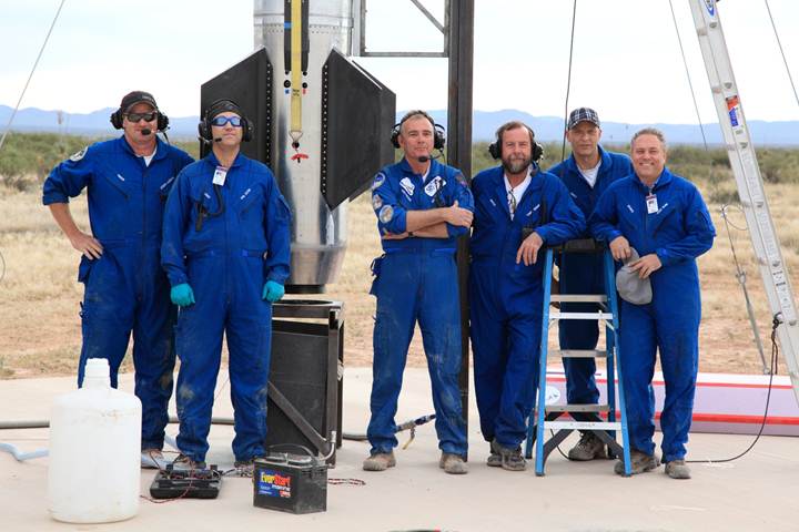
THE RIGHT STUFF
Following the demise of STIG A
back in February, we were faced with a dilemma. The fastest way back to flight
would have been to build another STIG A, 15” diameter, with just a few tweaks
to nudge her over the 100-km Karman line and claim our first space shot. In
retrospect this would probably have been a better course of action. Monday
morning quarterbacking aside, we decided to build STIG B, a 20” variant, so
that we could carry more massive and larger payloads to space. One of the
determining factors in this decision was that, even if we could nudge STIG with
small payloads into space under a waiver, NASA’s Flight Opportunities Program
was mandating that all flights under their banner be FAA/AST licensed flights
per 14CFR Part 431. If we had to license the vehicle anyway, we might as well
take advantage of the unlimited total impulse … and get our first taste of the
license regime.
So, a simple change in
diameter with a few enhancements … NOT!
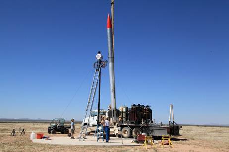
STIG B ERECTION ON LAUNCH STAND
The structure of the vehicle
was basically “start from scratch” although we got to keep much of our
electronics intact. We opted for 20” because it was the largest airframe we
could accommodate in our CNC equipment and that was plenty big enough at this
stage. Not long after we made this decision we hit our first major snag. The
propellant tanks were to be rated for 400-psig MAWP with proof pressures in the
500-psig range and burst pressures at 600-psig plus. This necessitated using
tube wall thicknesses of 0.190” in 6061-T6 and we had to fight a months’ long
battle to figure out how to heat-treat these post-welded to meet the desired
specifications. But even before that we hit another problem … availability of
material. Super-sized sheets are prevalent in US sales literature but
non-existent in reality. We had settled on 6½-ft long tanks for both LOX and
Ethanol and 20” diameter requires 63” wide material. We didn’t want to “stitch”
together spools or use an intermediate spool piece so we needed material that
was at least 84” long or more (we made the tanks 7-ft long so we could true
them up on the lathe (our limit!) x 63” or more wide. Nada! In the end we
sourced some super-sized sheets from Europe at significant cost above normal
and then to compound matters the sheets arrived damaged and had to be replaced.
This process caused us significant delay and our problems had only just begun.
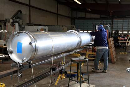
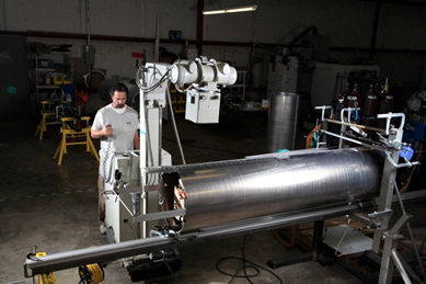
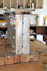
PROPELLANT TANK MODULE WELDING
Welding this
thickness of material with the standard AC TIG weld procedures that had served
us so well with the 15” diameter 0.125” thick tanks on STIG A proved to be
problematic. Weld porosity was the main problem especially near tacks
and it required much rework. Based on advice from a NASA welding engineer, and
after a lot of practice, James developed a procedure using DC TIG and a
home-made, semi-automatic welding rig that eliminated the porosity at the
expense of a few inclusions which were more easily repaired. We made full use
of our in-house X-Ray capability during this intense period of R&D. Solving
this part of the propellant tank issue was only the first part of the story.
X-RAY OF TANK SEAM WELD
We had built a hydraulic rig
for testing recovery system components (after the failure of a 5,000-lb
man-rated piece of hardware at 5,000-lb … no safety factor!) and we used this
to tensile test weld coupons from the new DC TIG process. We determined that we
needed every bit of the T6 temper on the longitudinal seam welds to meet the
burst pressure requirements and provide the necessary safety factor. This
required that we send the finished tubes, not yet capped, for solution heat
treat. There are not too many shops that have a drop-bottom oven and water
quench tank of the requisite size but we did eventually find one in Wichita KS.
Even this oven was pushed to its limit and the quench was somewhat uneven as
the cage was dropped into the water leading to a distorted tube. This we
remedied by taking the tubes to Baldwin in Dallas who re-rolled them to an
acceptable tolerance. Only after this were we able to weld the end caps and
inter-tank coupler on with the same DC TIG, X-Ray and inclusion repair process
as on the long seam. Now we have a T4 longitudinal seam (good) and a T0
circumferential seam (bad!) The solution is to artificially age the T0 to ~T5, and the T4 to ~T6 temper in our in-house heat treat
oven. This process, proven out by our hydraulic test rig produced the requisite
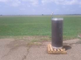
results in just a few hours. The burst test of the sample tank proved very
satisfactory at 675-psig and it failed at the circumferential weld as
anticipated. The proof test of the flight tanks to 510-psig was satisfyingly
non-dramatic and we have subsequently cycled these tanks dozens of time with
intermediate re-proof testing after flight.
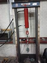
TENSILE TEST RIG BURST TEST SAMPLE
TANK
For the other airframe
sections where the weld was not critical and we didn’t require any pressure
capability beyond atmospheric, we used 0.125” and 0.90” wall sections made by
Argyle Industries in NJ. Their quality was more than acceptable but their automatic
welding process would not pass muster for pressure sections.
The nose cone of course
required a new mold for the 20” diameter … and it’s big! The shift from 15” to
20” diameter doesn’t sound like much but it’s deceptively larger. We used Air
Command International, our next door neighbors, for the nose cone and also the
composite fins. There was another learning exercise in making the fins. It is
hard to believe that something as heavy duty as the fin molds we had machined could
distort but at the elevated temperatures in the curing oven they do just that
and we now have some humongous C-clamps to hold the assembly together.
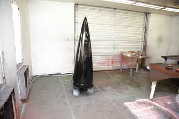
FIN
MOLD NOSE CONE – FIRST ARTICLE
There were two other issues
with STIG A that we wanted to address with STIG B; roll control and telemetry
dropout at altitude.
STIG and STIG A had
electrically actuated roll vanes for roll control and these had proved
problematic on two counts. Initially we had used a single roll vane and this
induced inertial coupling which led to a premature thrust termination and
ultimately loss of STIG after a recovery system failure. STIG A used dual roll
vanes in an attempt to eliminate this coupling problem but flight testing was
about to teach us another lesson. As we approached the transonic regime we
experienced a “roll control inversion.” This meant that the aerodynamic forces
from the roll vanes operated in the exact opposite direction to that
experienced subsonic. The result was that the vehicle went into a snap roll and
we exceeded the flight rule roll limit of 360-degrees/second. Our flight
control logic was to lock the roll vanes and the engine gimbals in the neutral
position and continue to burn until we exceeded any other flight rule limit,
which we did. With no active guidance STIG A
weather-cocked into the relative wind and exceeded our expected maximum IIP.
However, the vehicle still reached an apogee of 43-km and was recovered
reasonably intact. For the second flight we rotated the roll vanes around the
airframe to potentially eliminate any aero-effects on the fins downstream but
alas this was not the problem. We experienced the same transonic regime roll
control inversion and snap roll. However, this time we had allowed the engine
to continue to gimbal and STIG A achieved a full propellant depletion burn
which resulted in an altitude of 90+ km; our best effort yet and knocking on
the door of space. Unfortunately because of a recovery system problem, this was
the last flight for STIG A.
For STIG B we discussed a
software change to counteract the roll control inversion but opted for a change
in tactics. We knew that in the near future we would want pointing capability
and there was some concern that any asymmetric thrust at thrust termination
could lead to a pitch-yaw rotation that we could not counter. Therefore, we
decided to use some of the additional space afforded by STIG B’s larger
airframe to incorporate a cold gas thruster system using residual helium
post-boost. We had a cast aluminum ring fabricated with eight nozzles …
pitch+/-, yaw+/- and pairs of CW/CCW roll … and to this we mounted Parker 12-V
solenoid operated valves. We statically tested this on the vehicle by
suspending from the crane and it seemed to be more than adequate. In fact, so much so that we will likely introduce a modification to
permit fine control by regulating the inlet pressure.
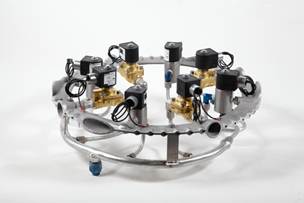
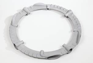
ACS MANIFOLD W. VALVES INVESTCAST ACS RING
The telemetry dropout issue
was something else that needed serious attention. There is something very
disconcerting about launching a vehicle, have it disappear from visual range
and then lose contact with it altogether. For many years we had been using
Esteem 195Ed-2 (900 MHz & 2.4 GHz) radios with good luck but they had not performed
well on STIG vehicles. Russ did a detailed analysis to check the link margins,
uplink and downlink, and determined that “we need more power Scotty” plus some
enhancements to the antennas and GSE. However, during ground testing we started
to experience communications issues with the Esteems and we never did quite
resolve this problem. It appeared, and got worse, we believe, after a firmware
change and it led to the adoption of the Ubiquity Rocket M900 radio.
Perversely, this is the same radio that is in the Esteem but it worked
perfectly straight out of the box confirming our suspicions about the firmware
on the Esteems.
To verify our choice of
hardware we installed the entire set-up in a fin can module and flew it on a
leased aircraft with the main flight computer inside. The system worked all the
way out to 100-km and should be good to 150-km plus when operated vertically.
The RTT (Remote Thrust Termination) system was also tested successfully out to
60-km and its required range is 30-km; the boost phase. The ground station used
a dual-polarized Ubiquity yagi antenna and the RTT used a Sure
helical antenna.
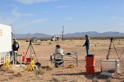
LAUNCH CONTROL AREA VIEW OF PAD
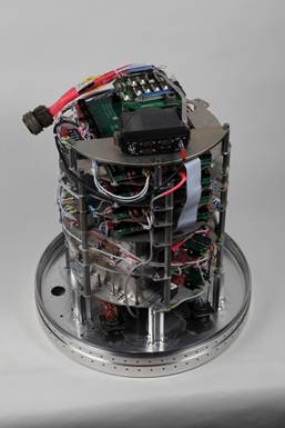
MAIN FLIGHT COMPUTER STACK
The main flight computer is
starting to look “busy” now. The additional driver requirements imposed by the
cold gas ACS and the need to provide trigger signals for multiple payloads
required us to install additional boards. A later addition to this stack will
be trace heating and/or blanket to keep the batteries and flight computer warm
during cold climate operations. We are still using the Diamond boards which
have proved very reliable with the only downside being long lead times for the
CPU board necessitating buying in batches larger than we would like and keeping
a “bin reserve.”
Having given the launch
license as one of the primary drivers behind the decision to build STIG B, we
should probably say a few words on that front. We have an excellent
relationship with FAA/AST built over more than a decade of collaboration that resulted
in multiple permits and waivers, both with extensions, for a variety of
vehicles in several locations. We had hesitated applying for our first license
imagining it to be a daunting task. In the final analysis it wasn’t so much
daunting as it was lengthy. We already had extensive documentation for the High
Power Class III Experimental Waivers for STIG and STIG A to draw on and the
only element of 14CFR Part 431 “Launch & Reentry of a Reusable Launch
Vehicle” that required much work was the EC analysis. We also had
significant experience with TAOS “Trajectory Analysis & Optimization
Software” and Missile Datcom for vehicle inertial property evaluation which
served us in good stead.
The analysis was no different
to that required for our Lunar Landers but, of course, our range with an errant
Pixel did not cover much area whereas STIG B could definitely reach out and
touch someone … in El Paso, Juarez not to mention a host of smaller population
areas. Having a million plus souls in your potential impact area does bad
things for your EC (Expected Casualty) value! The process is simple
if mind numbingly tedious. We assume that the vehicle goes AWOL at any time
during the boost phase and heads off in random directions with the gimbals
locked in some unfavorable position. The vehicle then could either tumble and
crash short range or execute a beautiful maximum range gravity turn sometimes
in the direction of densely populated areas. The impacts were plotted onto a
population density map of the area and factors such as explosive debris from residual
propellant, impact angle, skip and bounce were used to determine the “body
count.”
The initial
runs were on the basis of “everything fails, every time!” This was unrealistic
and resulted in an EC that was about twice the permitted limit. One
feature of our flight safety system that has been ever present and 100%
successful is the thrust termination system. We monitor several parameters to
determine whether or not to terminate thrust. Two of the most important are the
Ground Speed and the Max Range IIP (Instantaneous Impact Point). The latter is
basically a conservative estimate of “where would I land if I flew with current
vehicle vector accelerating for another full second before the thrust was
terminated.” For Spaceport America the Flight Hazard Area was initially
determined to be a circle of 7-km radius centered on the launch pad. Sir
Richard Branson’s pretty new hangar building was 7.2-km distant. J Of course, one can’t
assume that a flight safety system that has a prior 100% success record is
going to remain so indefinitely and we agreed a binomial distribution approach
which was more than optimistic enough to meet the required EC limit.
As a final
footnote to the license process I have to add that we could not have asked for
a more cooperative and helpful group than our support team at FAA/AST. Our POC
was John Howell who did an absolutely stellar job of keeping things on track in
Washington and I spent countless time with Steve Millard on the trajectory and
safety analysis. In the field David Gerlach has been the FAA/AST observer and
it was invaluable to me as the ASO (Armadillo Safety Officer) to have his
advice and counsel. I said final but I should also say a word about Spaceport
America and their support team. We are undoubtedly the most prolific launch
company from their new facility and we’ve both learned a lot over the past
couple of years. Each mission is smoother than the last and the Spaceport
America team could not be any more professional or supportive. In fact, we now
hold the Mission Readiness Reviews in their Las Cruces offices and we chose Las
Cruces as our base of operations partly on this fact and also for the wide
range of accommodation and services. We do wish that it was several hundred
miles closer. That drive out on I-20 and I-10 seems to get longer each trip
especially towing the 40-ft rocket and launch control trailer!
One recurring theme above is
that of recovery system problems. Phil Eaton has been our lead on this working
closely with Lee Hardesty of Applied Deceleration Technology, Wamore Inc of
Phoenix and with input from folks at Strong Enterprises, JPL and others. Phil
has written a diatribe on our recovery system learning curve which was posted
to aRocket a little while ago. We’re going to post
that report, which covers the entire STIG family of vehicles, in a separate
post directly after this one because it is quite lengthy in its own right and
attach some photographs and video.


